3D Printing
3D Printing.
Merlin Fob
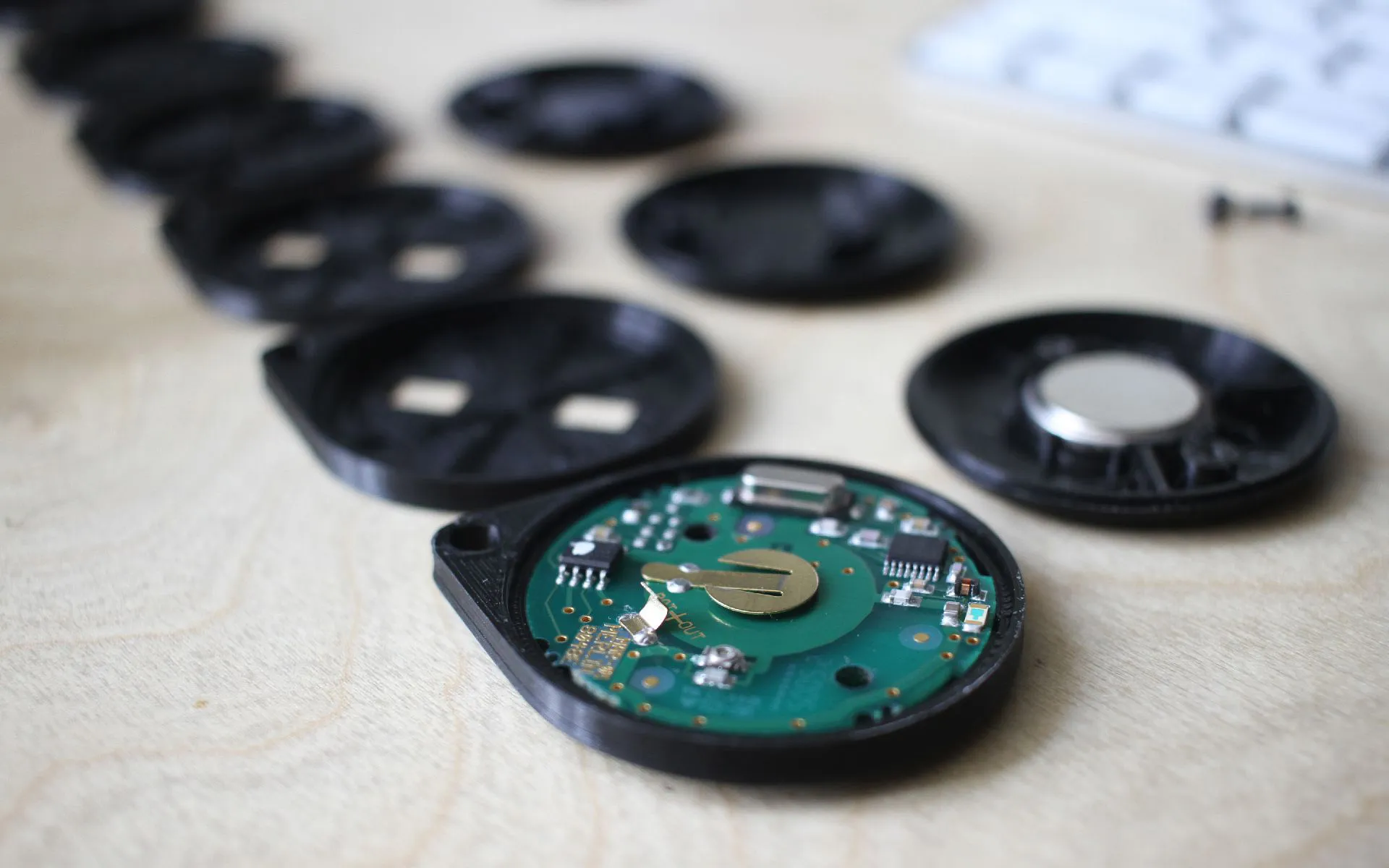
I was tasked with fabricating a replacement housing for Merlin M842 remote control for a garage door. Given that the device is most commonly carried on a key chain or thrashed around in a car glovebox, the housing ends up taking a beating with age and a replacement can cost as much as $60 to $90. My goal was to create a competent replacement that would:
- be user serviceable (accessible battery compartment)
- have the led indicator visible
- have a slimmer profile than the original
- be easy to manufacture using a hobby grade FDM 3D printer
- Didn’t take too long to design or print
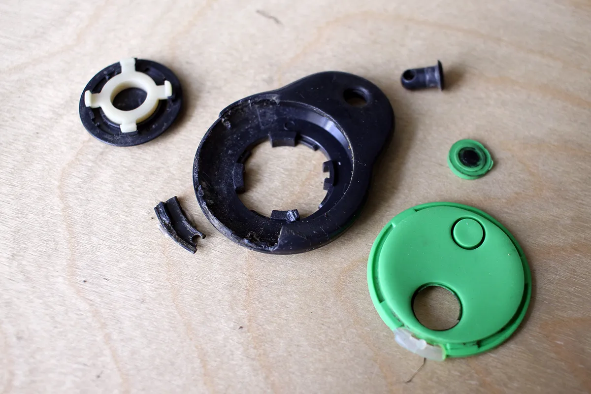
The circuit board of the remote is a circle, the battery is centered on the back and the buttons are simple printed contacts that get shorted by the rubber buttons. The original rubber buttons were ripped and I ended up salvaging buttons from a calculator that had conductive carbon coating on the bottom.
My design essentially boiled down to two components – the “housing” that’s the main body holding all the components and has the keychain loop, and the “cap” that holds the battery in place.
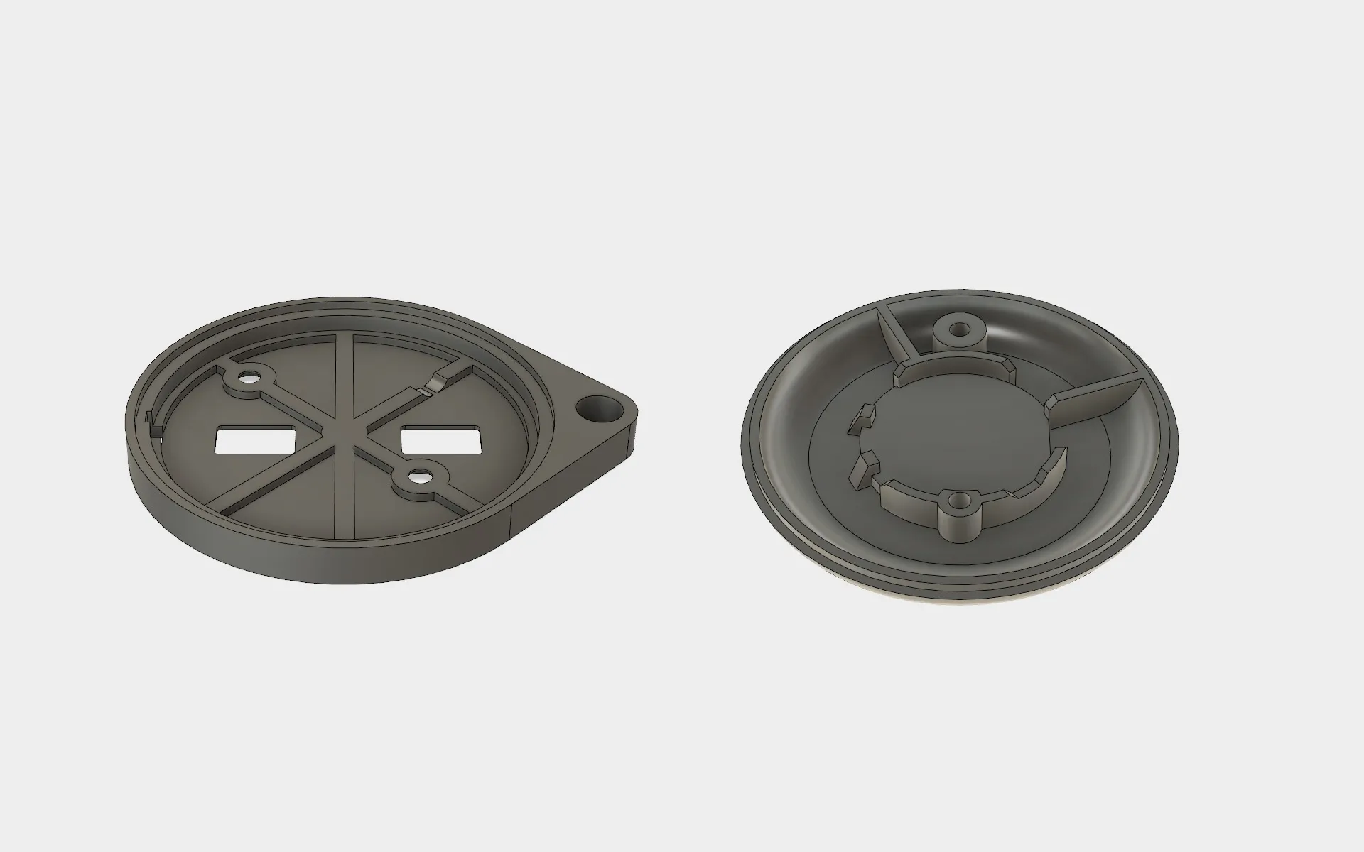
The design went through 6 iterations on the main body and 3 iterations on the cap. To further “slim down” the profile I made the cap have rounded edges to give a thinner feel to the whole assembly.
Getting the circuit to sit right in the housing was easy, the circuit is pretty symmetrical and key components sit at neat 45 degree angles to everything. The main challenge was to get the tolerances right on the cap for the battery to be centered on the power connector. The led indicator is simply hot glue melted through a hole in the housing. The circuit board had two convenient holes for me to thread screws through to avoid having to design a locking mechanism.
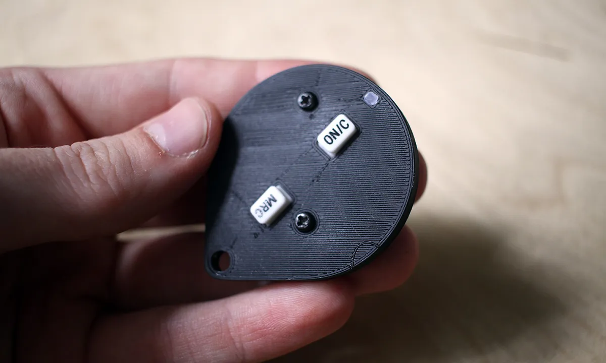
While the calculator buttons look funky and unique, I would ultimately prefer for the buttons to be hidden under the housing. They’re too easy to press accidentally or pull the rubber out of the housing. The best alternative would be to solder in some low profile hardware buttons and use the flexibility of the housing to press them through the plastic.
If you own one of these fobs and yours is falling apart, feel free to download the files and print them on your own. There’s no guarantee that the buttons that you will use be of the same dimensions, so I provided a version with the center point of the buttons for you to cut away (physically or digitally) as much material as you need for the buttons you’ll end up using.
Wing
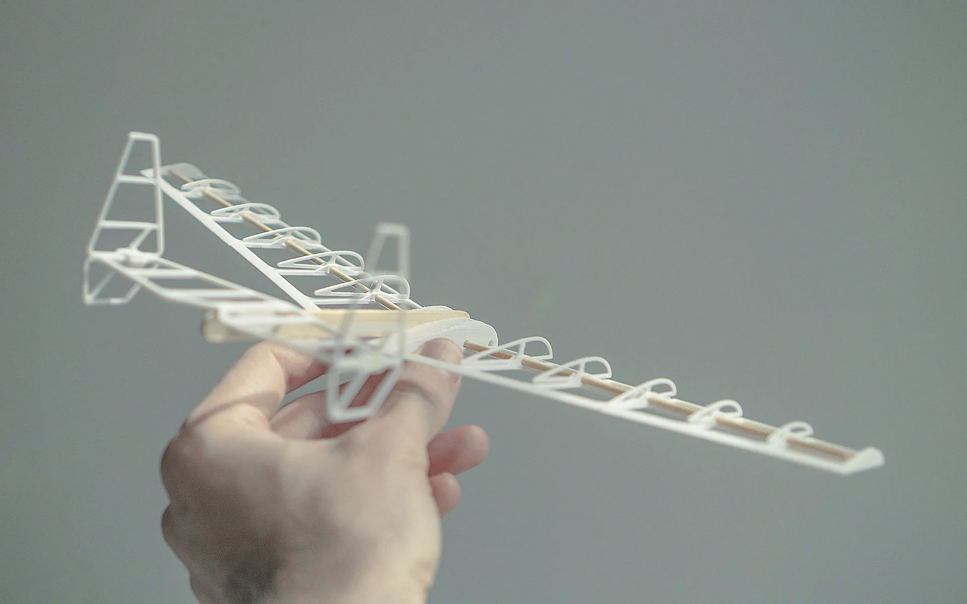
A 3D printed fixed wing glider. Designed to be printed on a minimal 100x100mm printing bed.
Hsv Led
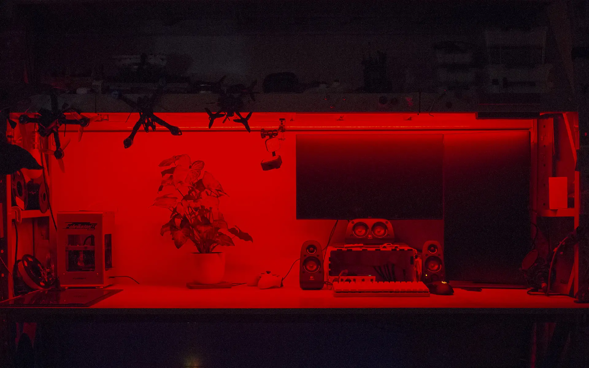
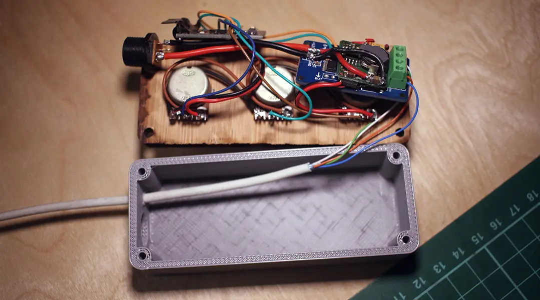
An arduino controlled light strip for my former workspace. It used off the shelf components, 3D-printed and lazer-cut parts. It had 3 knobs that controlled color and brightness using HSV mapping. Code and STL files available on the project github page.
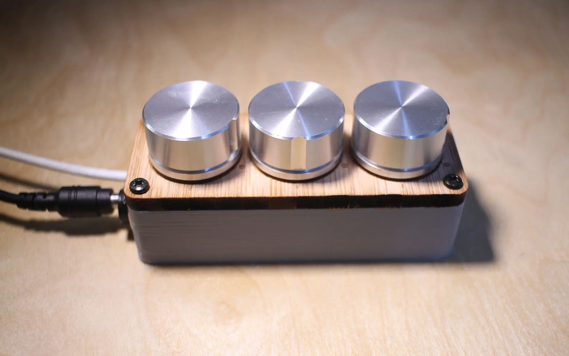
Parts
- P9813 LED controller
- 1x Arduino nano
- 3x Analogue Pots
- 1x 5v or 3.3v (depending on your Arduino) Voltage regulator
- 1x 12v power input jack
- 1x 3D printed shell
- 1x Lazer cut faceplate
Dependancies:
- FastLED Library
- ResponsiveAnalogRead Library
- ArduinoAnalogueSmooth Library
I had particularly low quality potentiometers, so the signal is over-filtered. I would use digital rotary encoders if I were to improve it.
Eachinevr006
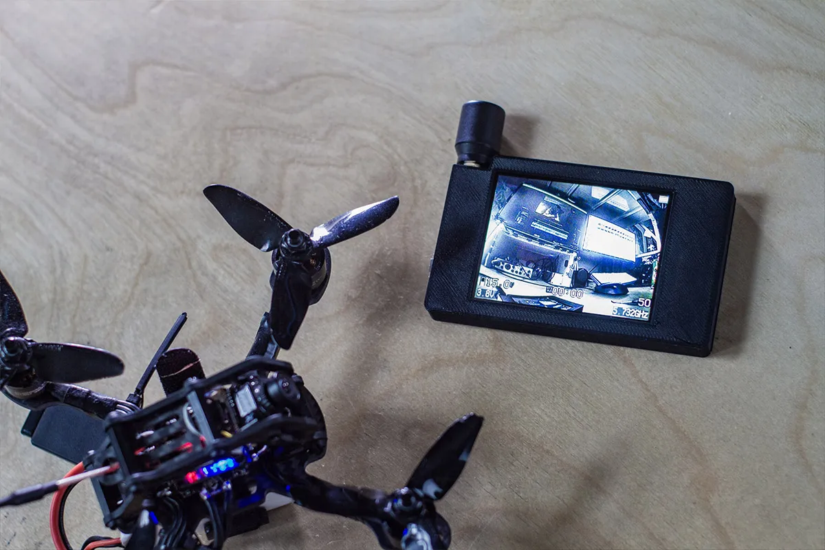
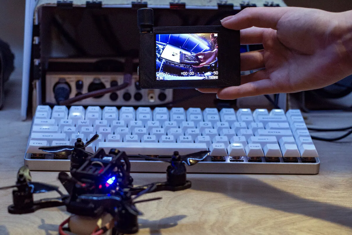
This project offers 3D printing files and instructions to re-house the screen and electrical components extracted from a cheap FPV headset Eachine VR006 to use as a stand-alone spectator screen for Drone Racing and other RF hobby applications.
A video version of this guide is available on youtube. 3D CAD models licensed under CC BY-NC-SA 4.0
Guide
Step 1
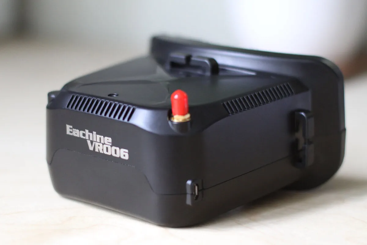
Remove the SMA cover and the retaining brass nut.
Step 2
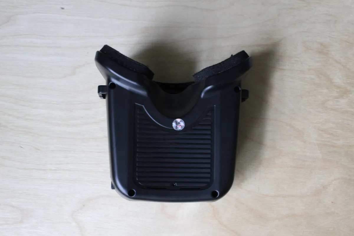
Underneath, unscrew 4 phillips screws and lift the top half of the plastic body.
Step 3
The battery is held in place with a piece of foam and double sticky tape. Remove the foam and carefully cut along the tape with a craft knife to avoid prying the lipo battery. Remove the control board and the fresnel lens. The screen assembly should freely slide out of the housing.
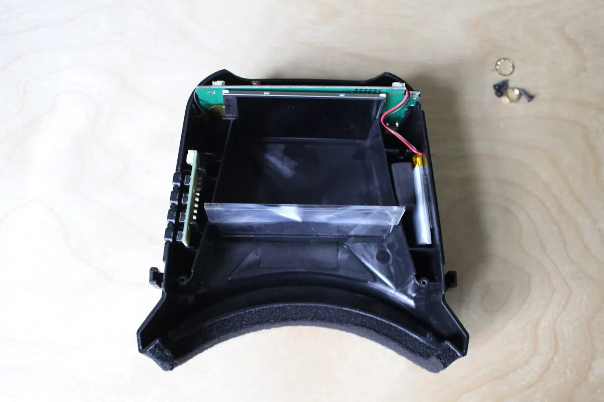
Step 4
Be careful removing the screen, as it's not attached to the circuit board. Pull them gently together to avoid damaging the ribbon cable.
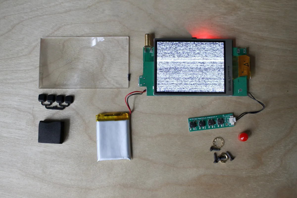
There are two variants of this board - the "diversity" version with two antennas (not real RX diversity) and the single antenna version I have here, my case design is for this version.
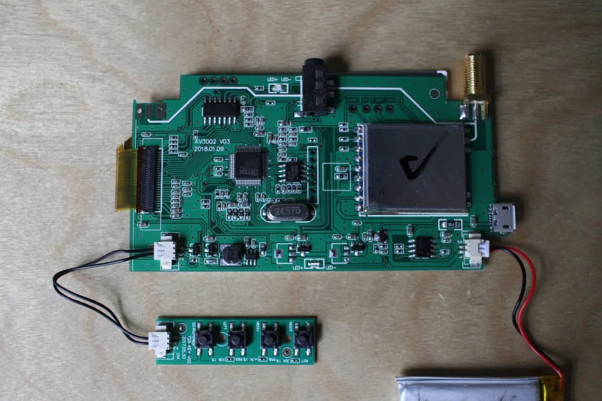
Step 5
Next, you'll tape up the exposed breakout pins to avoid short circuiting them when you secure the screen to the surface (the back of the LCD is metal).
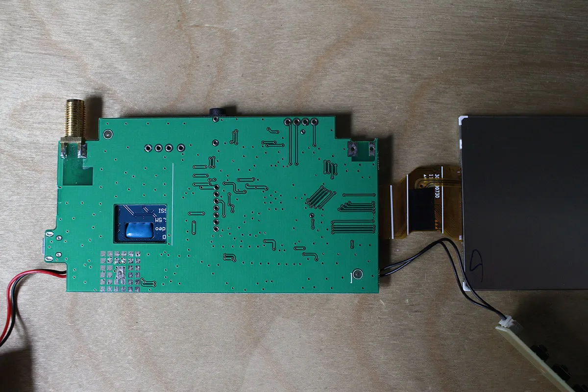
Cut some pieces of electrical tape to cover the breakout pins and gently press the screen onto the board to secure it with double sticky tape. Use double sided tape, foam tape will make the assembly too thick.

Step 6
Navigate to /STL/, download and 3D print the housing.
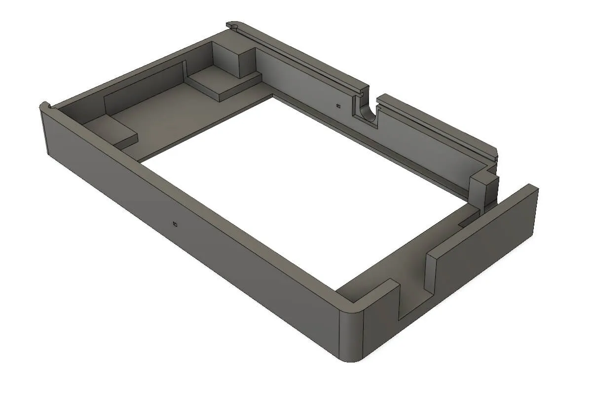
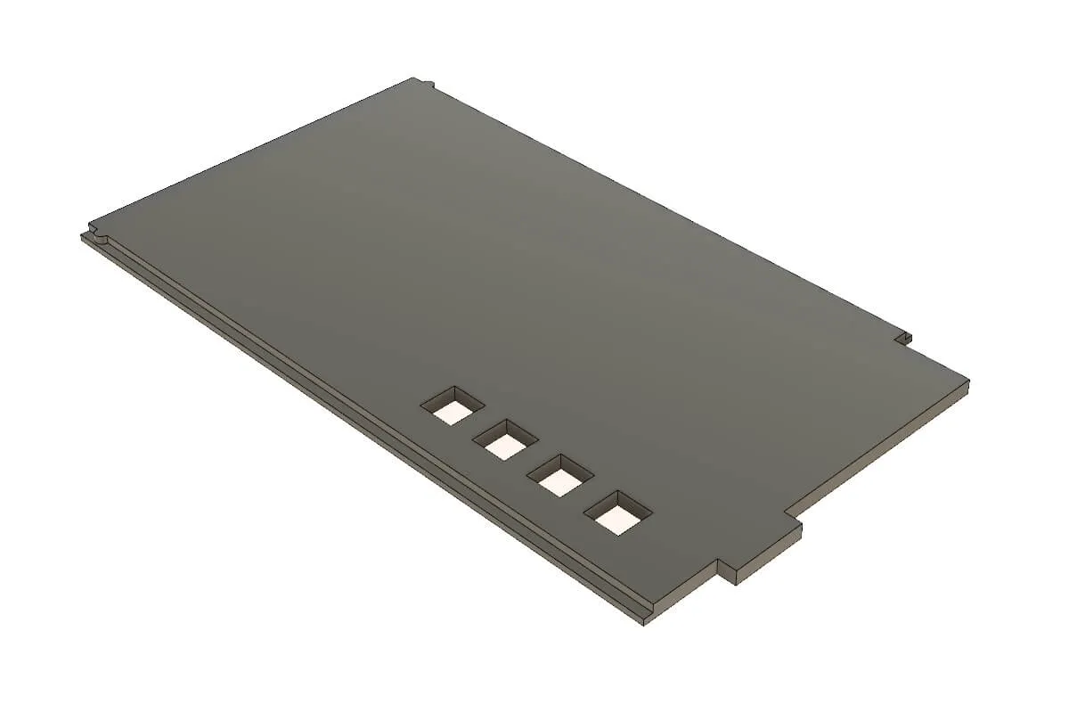
I created this to fit on a 10x10 printing platform, which is common among lowest-end printers. Due to this, the USB charging port sticks out a bit. If you want to make it flush with the side of the case, simply extrude the right wall by 3mm to the left.
Step 7
Remove the metal frame from the LCD panel. It will only get caught in the ridges of the 3D print and may actually damage your screen.
Step 8
Slot the assembly into the body of the case, ribbon cable side first, carefully allowing the case to bend it over the edge.
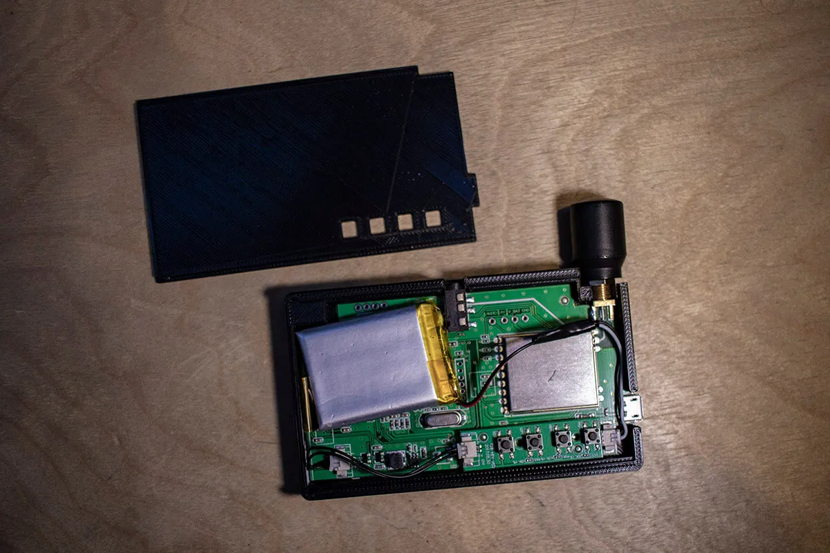
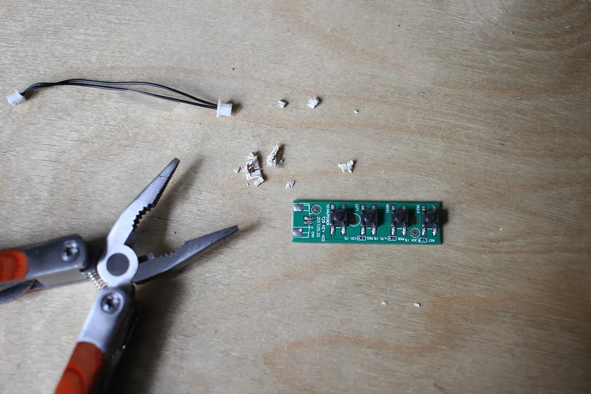
Step 9
De-solder the connector from the control board and re-attach the cables in order for the buttons to fit into the rear panel holes. Make sure to note which cable goes where, they're both black.
Step 10
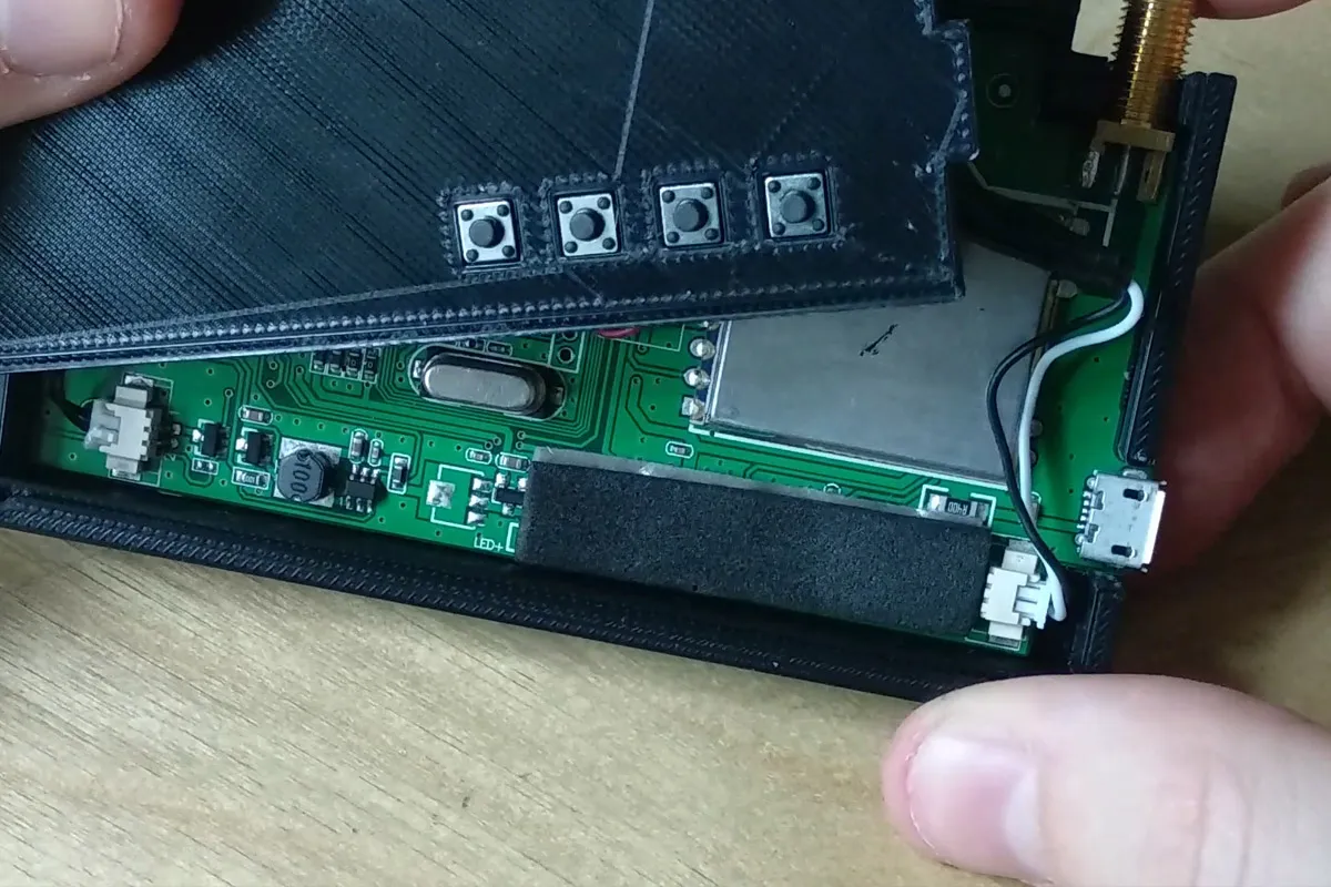
Add some foam padding to the motherboard to sit against the control board to prevent it from sinking into the case when pressing the buttons.
Step 11
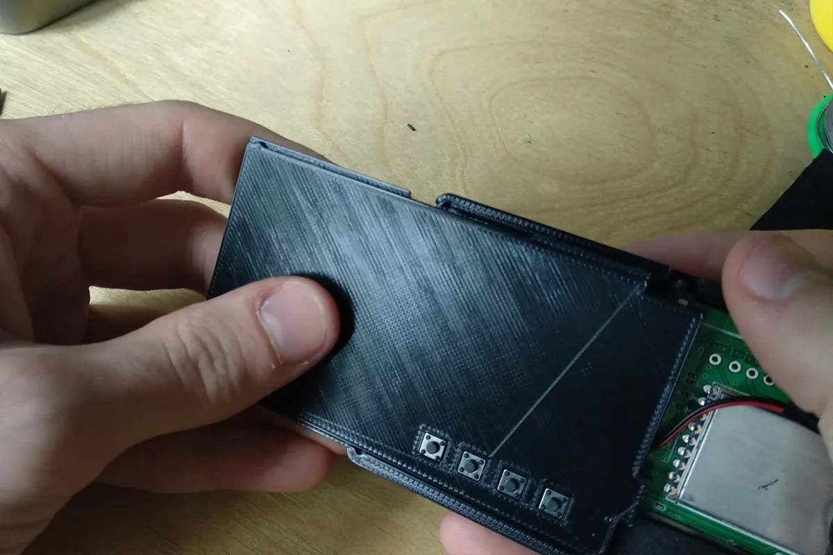
Slot the rear cover into the bottom rail, aligning the top rail gaps then push it in to mesh both rails and slide the cover on.
Done!
Your screen assembly is now complete! Happy flying!